Previous:No more!

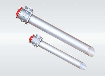
TF series external self-sealing oil filter
The filter is installed at the suction port of the oil pump to protect it and other hydraulic components from pollution impurities,to improve the cleanliness of the hydraulic system.The filter can be directly installed on the top,side or bottom of the tank,filter cylinder immersed in the tank below the liquid level,while filter head exposed outside the tank,and it’s equipped with self-sealing valve,by-pass valve,filter pollution blocking transmitter and other devices,so that when r
Ask For Quote
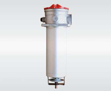
TF series self-sealing oil suction filter outside the box
The filter is installed at the suction port of the oil pump to protect it and other hydraulic components from pollution impurities,to improve the cleanliness of the hydraulic system.The filter can be directly installed on the top,side or bottom of the tank,filter cylinder immersed in the tank below the liquid level,while filter head exposed outside the tank,and it’s equipped with self-sealing valve,by-pass valve,filter pollution blocking transmitter and other devices,so that when replacing or cleaning filter element,the oil in the tank will not flow out.Our products are novel in design,easy to install,large oil capacity,small resistance,easy to use and maintenance.
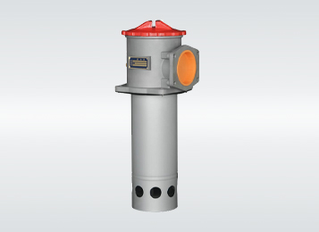
Application
widely used in hydraulic systems such as heavy machinery,mining machinery and metallurgical machinery.
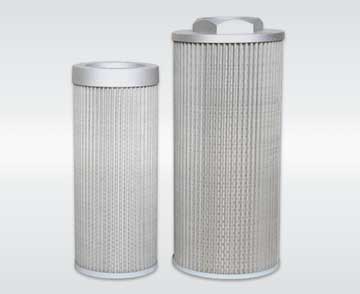
Filter medium
water and ethylene glycol in hydraulic oil
| model | nominal flow rate (L/min) | filtration accuracy (μm) | drift diameter (mm) | original pressure loss (MPa) | transmitting device | Connection:tube/flange | weight (Kg) | filter element model | |
|---|---|---|---|---|---|---|---|---|---|
| (V) | (A) | ||||||||
| TF-25x*L-C/Y | 25 | 80 100 180 | 15 | <0.01 | 12 24 36 220 | 2.5 2 1.5 0.25 | 管式 | 0.4 | TFX-25×* |
| TF-40x*L-C/Y | 40 | 20 | 0.45 | TFX-40×* | |||||
| TF-63×*L-C/Y | 63 | 25 | 0.82 | TFX-63×* | |||||
| TF-100×*L-C/Y | 100 | 32 | 0.87 | TFX-100×* | |||||
| TF-160×*L-C/Y | 160 | 40 | 1.75 | TFX-160×* | |||||
| TF-250×*F-C/Y | 250 | 50 | 法兰 | 2.6 | TFX-250×* | ||||
| TF-400×*F-C/Y | 400 | 65 | 4.3 | TFX-400×* | |||||
| TF-630×*F-C/Y | 630 | 90 | 6.2 | TFX-630×* | |||||
| TF-800×*F-C/Y | 800 | 6.9 | TFX-800×* | ||||||
| TF-1000×*F-C/Y | 1000 | 8 | TFX-1000×* | ||||||
| TF-1300×*F-C/Y | 1300 | 10.4 | TFX-1300×* | ||||||
Note: * refers to filtration accuracy.If the medium is water-glycol,nominal flow rate is 160L/min,filtration accuracy is 80μm,with zs-i transmitter,the filter model is TF* BH-160x80L-C,and the filter element model is TFX.BH-160x80.
Connection Size
1、tubular (outlet threaded link)

2、 flange (outlet flange link)

Table I、 TF-25 ~ 160 threaded connection size
| model | size(mm) | ||||||||||||
|---|---|---|---|---|---|---|---|---|---|---|---|---|---|
| L1 | L2 | L3 | H | M | D | A | B | C1 | C2 | C3 | h | d | |
| TF-25 × * L-C/Y | 93 | 78 | 36 | 25 | M22 × 1.5 | Φ62 | 80 | 60 | 45 | 42 | 42 | 9.5 | Φ9 |
| TF-40 × * L-C/Y | 110 | M27 × 2 | |||||||||||
| TF-63 × * L-C/Y | 138 | 98 | 40 | 33 | M33 × 2 | Φ75 | 90 | 70.7 | 54 | 47 | 10 | ||
| TF-100 × * L-C/Y | 188 | M42 × 2 | |||||||||||
| TF-160 × * L-C/Y | 200 | 119 | 53 | 42 | M48 × 2 | Φ91 | 105 | 81.3 | 62 | 53.5 | 12 | Φ11 | |
Table II、TF-250~800 flange connection size
size| model | size(mm) | ||||||||||||||||
|---|---|---|---|---|---|---|---|---|---|---|---|---|---|---|---|---|---|
| L1 | L2 | L3 | H | D1 | D | a | b | n | A | B | C1 | C2 | C3 | h | d | Q | |
| TF-250 × * F-C/Y | 270 | 119 | 53 | 42 | Φ50 | Φ91 | 70 | 40 | M10 | 105 | 81.3 | 72.5 | 53.5 | 42 | l2 | Φ11 | Φ60 |
| TF-400 × * F-C/Y | 275 | 141 | 60 | 50 | Φ65 | Φ110 | 90 | 50 | 125 | 95.5 | 82.5 | 61 | 15 | Φ73 | |||
| TF-630 × * F-C/Y | 325 | 184 | 55 | 65 | Φ90 | Φ140 | 120 | 70 | 160 | 130 | 100 | 81 | 15.5 | Φ102 | |||
| TF-800 × * F-C/Y | 385 | ||||||||||||||||
| TF-1000 × * F-C/Y | 485 | ||||||||||||||||
| TF-1300 × * F-C/Y | 680 | ||||||||||||||||
Note:The oil outlet flange,installation connecting bolt,sealing gasket and other accessories required by this product are matched with this product.Users only need to prepare Q pipe welding.The connector of transmitter is M18 x 1.5,plug wire can be provided if the transmitter is not required.
Water from the inlet into the filter,first through the coarse filter element assembly to filter out larger particles of impurities,and then to the precision filter screen to filter out small particles of impurities,clean water from the outlet discharge.In the filtration process,the impurities in the inner layer of the fine filter gradually accumulate,and a pressure difference is formed on both sides of it.When this pressure difference reaches a preset value,the automatic cleaning process begins:the sewage valve opens and the hydraulic motor chamber and hydraulic cylinder of the main assembly releases pressure and drains the water.The pressure of the hydraulic motor chamber and the sewage suction pipe drops sharply.Due to the negative pressure,the dirt on the inner wall of the fine filter screen is absorbed through the suction nozzle,which flows into the hydraulic motor chamber by the hydraulic motor and is discharged by the sewage valve,forming a sewage suction process.When the water flows through the hydraulic motor,it drives the sewage suction pipe to rotate,and the hydraulic cylinder piston drives the sewage suction pipe to do axial movement.The sewage suction component completely cleans the inner surface of the entire filter screen through the combination of axial movement and rotary movement.The whole process will last for tens of seconds.The sewage valve closes at the end of the wash,the increased water pressure causes the cylinder piston to return to its original position,and the filter begins to prepare for the next flush cycle.In the cleaning process,the normal filtration work of the filter is uninterrupted.


